What is the frequency response or natural frequency of the sensor?
Questions regarding frequency response generally arise due to combinations of three topics of interest. Typically, sensor users need to know: one, how quickly the sensor will respond to changes in input (force, torque, pressure, acceleration, etc.), especially in dynamic system loads. Two, how quickly the sensor will reach 63.2% of FSO (time constant of the sensor) when exposed to a full-scale pressure input from zero instantaneously. And, three, what the modal frequency analysis of the sensor will be when subjected to vibrational loads.
While all of these are related concepts, especially mechanically, they are not entirely the same. Answers will vary based on pressure range, sensor design (monolithic diaphragm deflection or isolation diaphragm with load transfer to bending beam, as an example) and the electrical output provided by the sensor. The first two questions are both mechanical and electrical. Depending on whether the electrical output of the sensor is ratiometric mV/V (no electronics), amplified (voltage or current output) or digital (CANBus, I2C, RS232), the answer will be quite different if the mechanical design is held constant.
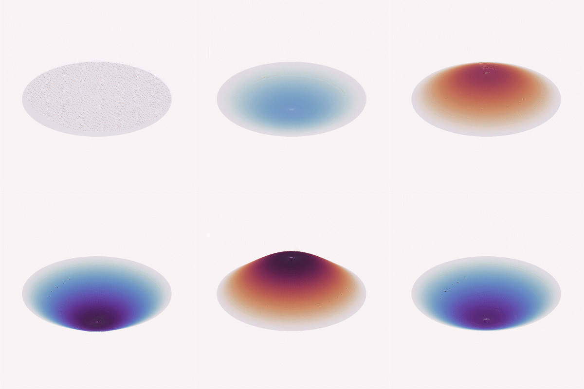
Mode (0, 1)

Mode (2, 1)

Mode (0, 2)

Mode (3, 1)

Mode (1, 2)
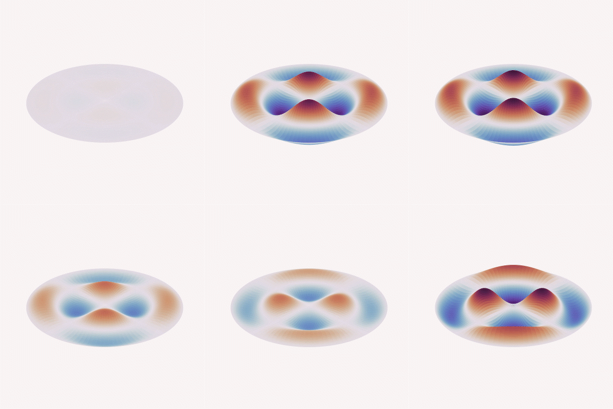
Mode (2, 2)
Typically, the mechanical portions of the sensors offer frequency responses in the tens of thousands of Hz. For example, 12kHz at 5000psi for a 0.5-inch diameter diaphragm, or 2.5kHz on a 100 psi design. For mV/V sensors, the electrical response will track very closely to the mechanical response. Meanwhile, the electrical response of a standard 0-5 V DC output non-isolated voltage amplified sensor will fall in the 2-3kHz range. The response will be slower for isolated voltage (1-2kHz) and even more slow for digital (200-900Hz). This will impact both the speed at which the sensor’s output responds to dynamic changes in pressure (in the case of pressure transducers) and the speed at which the sensor reaches a 63.2% FSO solution, even though the diaphragms would mechanically respond in identical ways.
Meanwhile, when looking at the sensor’s behavior in vibration applications, the acceleration response, structural/nodal analysis, etc. is impacted almost entirely by the mechanical design, and begins with the modal analysis of the sensing element based on complex differential equations and known plate or beam theory.
Since frequency response and acceleration performance equations always take into account material stiffness values (“D” or “k,” depending on the design or formulas used), the mass of the total system (e.g., a mass/spring damper system in load cell applications or the mass density of a compressed fluid on a diaphragm in pressure applications) and require assumptions in boundary conditions (clamped or free), the derived value of the frequency response will always be theoretical and limited in usefulness. It will always be necessary to validate the response through testing within the end-user system to determine if the performance meets system measurement or control requirements.